Motor Controller Challenge
Overview
Objective: Create a position controlled motor controller
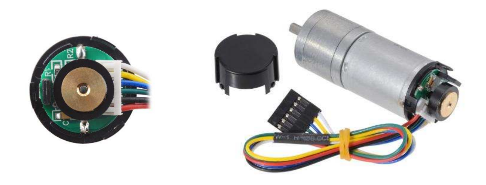
In this challenge, we will create a position controlled motor controller. We will be controlling the Pololu 25d HP12 gear motor.
This training includes both electrical and programming components.
Note
Programmers: Knowing the electrical components and wiring diagrams are beneficial when it comes to debugging
Electrical
Objective: Familiarize yourself with reading datasheets and basic wiring.
- This is the list of materials you will need:
Arduino R3 Uno
Breadboard
Jumper Wires
Pololu 12V HP Motor
Motor Driver (you need to figure this out)
Power Supply
Safety
When dealing with electrical components it is always important to practice safety.
Note
If you are unsure of something, ask questions! This is not an exam.
- DO NOT
Connect Ground and Voltage wires
Touch Ground and Voltage wires when the cirucit is powered
Let High current (more than 5A) continually flow through circuit
- DO
Look at the datasheets
Double check connections
Find the motor driver
We have included datasheets in this folder for various motor drivers and the Pololu Motor. Our LEXO uses a 24V LiPo battery. We won’t be using the 24V battery to power our system for testing purposes, but for the sake of this part let’s pretend we are.
Note
An important part of reading a datasheet is ignoring uncessary information/diagrams, identify and focus on the important factors.
Find 1: Motor
Figure out the motor voltage and current.
Find 2: Battery
Figure out the battery voltage and current.
Testing Motor
Now we will test the motor just to make sure that it is operational. Power your Arduino with a laptop or PC, and connect the motor GND (black) to an Arduino GND pin using a jumper wire. Then connect the motor power (red) to the Arduino 5V. Does the motor spin? If yes we can continue to the next part.
Wiring
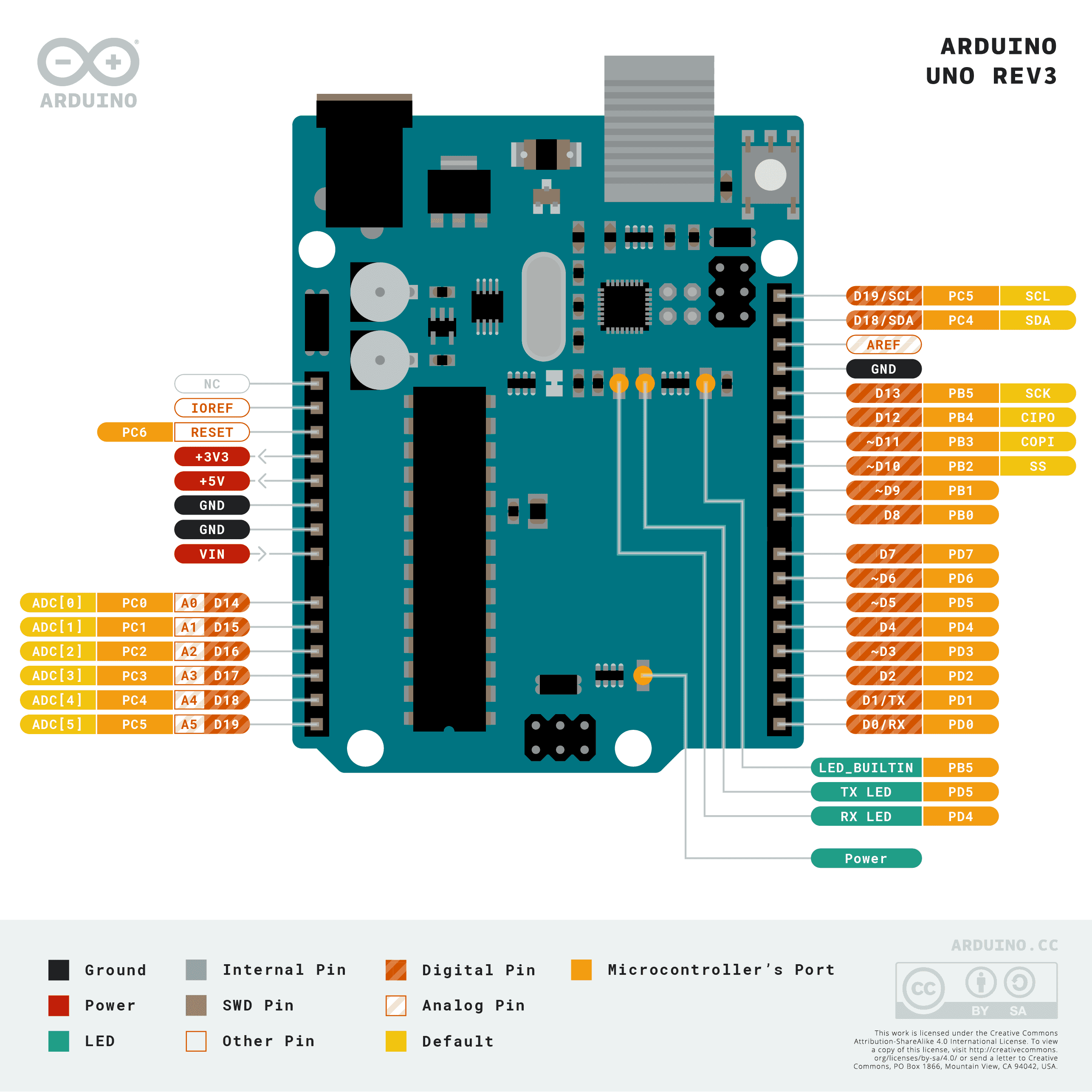
Now let’s begin to wire all the components together. There is an included Arduino pinout above.
Disconnect GND and V5 from the motor
Connect GND on Arduino to - on Breadboard
Connect V5 on Arduino to + on Breadboard
Connect motor GND and power to the motor driver MA and MB respectively
Connect motor Encoder A to pin 2 on Arduino and Encoder B to pin 3
Connect motor Encoder VCC to the + on the Breadboard
Connect motor driver (GND, PWM, and DIR) to Arduino (GND, 9, and 10)
Connect thick wires to motor driver VB- (black) and VB+ (red). This will later connect to the power supply.
Testing Circuit
Have someone double check all the connections before connecting the VB- and VB+ to the power supply!
Once everything looks good, plug in the power supply and turn it on to make sure that it is 12V. Power it off and connect the VB- and VB+ wires to GND and power on the power supply with the alligator clips. Turn on the power supply.
There are two buttons on the motor driver labeled MA and MB. Press one at a time to spin the motor in a direction. Make sure the motor is able to spin both directions. If it’s hard to tell the direction, you can just put a piece of electrical tape on the part that spins.
Programming
This part of the training will familiarize you with the basics of PID controllers, rotary encoders and Arduino.
Learn Encoders
In simple terms an encoder is a sensor that can indentify the direction and number of rotations of a system, in our case a motor.
Encoders in more detail
A rotary encoder is a type of sensor that alternates between high and low voltage (example 5V and 0V). If you check the motor data sheet, you will see there are two discs. Each disc will alternate between high and low when you spin the motor. The direction that the motor spins can be determined by which disc switches voltage first. Here is a useful video that explains encoders in simple terms.

Testing Encoder
Let’s test if the rotary encoder is working using the TestEncoder file. Download the program and open it in Arduino.
Make sure to define ENCA as pin 2 and ENCB as pin 3. Once that’s done, verify and upload the program then open the serial monitor (Tools > Serial Monitor). Rotate the encoder left and right to see if the two values change, if they do then the encoder should be working. Another test you can try is to use the serial plotter instead of the serial monitor to see the graphs of the encoders.
Testing Position Control
Next we will test if we can record position using the encoder. Download the TestPosition and open it in Arduino. Repeat the process for defining ENCA and ENCB. Verify and upload the program then run the serial monitor again. When you spin the encoder the position should increase or decrease depending on the direction it’s turned. If this happens then we know we’re able to read the position correctly.
Learning PID
A common way to control motors is by using a PID controller, which stands for Proportional, Integral, and Derivative. In simple terms, a PID controller is a control looping mechanism that continuously tries to achieve some target value. For example, if you are in a car and have cruise control set to 60mph, but you start going down or uphill. A PID controller is used to account for those differences to make sure the car keeps the set target of 60mph. Here is a brief video to better explain the topic and math.

PID controllers are a standard control algorithm in multiple industries. We will be using a PID controller in the next section to control the motor more precisely beyond just spinning forward and backward.
Writing PID Controller
Download the SetMotorTest and open it in Arduino. You will need to define the pins you used for ENCA, ENCB, PWM, and DIR. Make sure you have PWM connected to a digital pin that is marked with a “~”. Uncomment and write the code to produce the proportional, integral, derivative, and control signal.
Testing PID Controller
Lines 30-32 have the PID constants that you will need to adjust to hit the target on line 26. Try adjusting the PID constants until you are able to hit the target without overshoot or oscillation. You will need to connect the power supply to the motor GND and power and VB+ and VB- again for this step and the next step.
Calibrating PID Controller
Once you are able to hit the constant target, you should try a target that changes over time. Comment out line 26 and uncomment line 27. Repeat the steps you took in part V to make sure you can match the sinusoid as closely as possible without oscillation or overshoot. After this step you will have successfully controlled a motor. Congratulations!